Published
In this short post I'll explain how I set up a HomeKit compatible temperature and humidity sensor with a ESP8266 chip, Homebridge, and an AM2302 sensor
After yet another "I'm cold!" from my girlfriend, as an experiment I decided to track temperature and humidity in the house. As I already have HomeBridge up and running, I wanted to connect the sensor to the Home app on my iPhone.
I ended up flashing arendst/Tasmota on an ESP8266 NodeMCU I had laying around.
I'm not an expert in electronics, but I like to tinker so I'll stay out of things I don't know, and I'll point to reference material instead.
Parts list
- ESP8266 NodeMCU
- AM2302 temperature and humidity sensor
- A 4.7K - 10KΩ resistor
- Jumper wires
- Breadboard
Flashing Tasmota on the ESP8266
To flash the board I used
tasmota/tasmotizer. This
is a Python package you can install with pip and it comes with
a GUI.
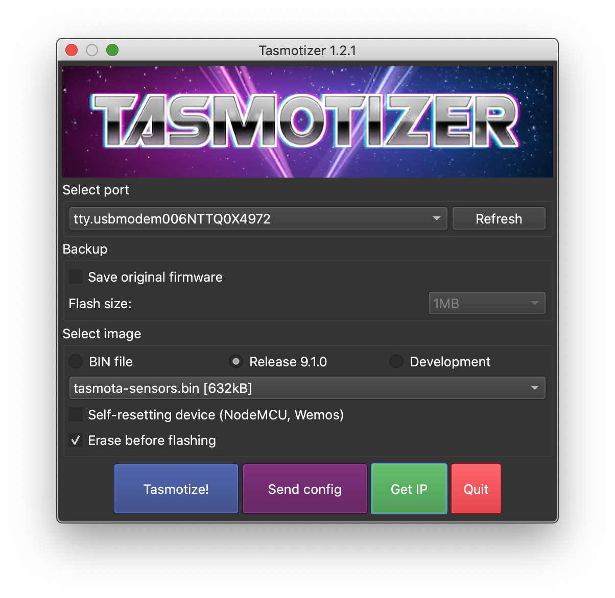
# set up a virtualenv for good measurepython -m venv venvsource venv/bin/activate# install and run tasmotizerpip install tasmotizertasmotizer.pyAt this point connect the board to your computer, select the
correct port, select the tasmota-sensors.bin image from the
dropdown, and click Tasmotize!
You can read a lot more about what you need to flash the board and how to do it in this section of the Tasmota documentation.
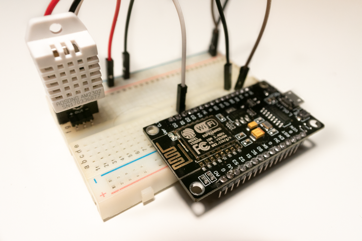
The circuit
The project is very simple, and the circuit I built is also extremely simple.
-
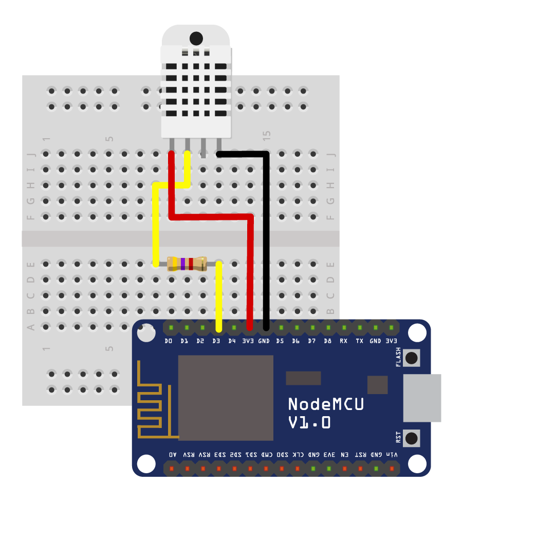
The AM2302 sensor requires a voltage in the range 3.3V - 5.5V, the recommended supply voltage is 5V. I used a voltage of 3.3V, but should the sensor not work for you, try going up to 5V.
-
Connect the AM2302 data pin to
D3/GPIO 0. -
You should add a 4.7K - 10KΩ resistor between the board and the data pin, you won't melt anything but it may not function correctly.
-
Lastly connect the
GNDpin on the board to the-(minus) pin on the AM2302.
Configuring the sensor in Tasmota
At this point, you're ready to boot the chip, and to configure Tasmota. The first time you boot, the ESP8266 will create a local network you can connect to to fill in Wi-Fi SSID and password.
Note that these chips can only connect to 2.4GHz networks, and that some of the changes will require restarts.
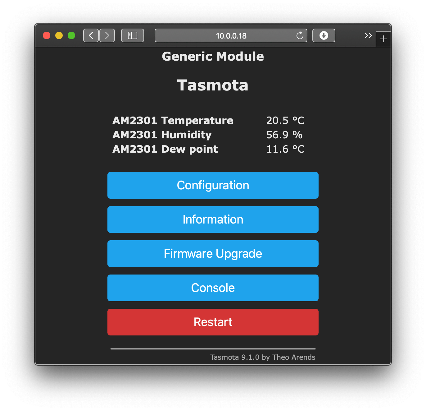
After you've set up the Wi-Fi, navigate to the IP address of the sensor in your browser.
Find and click on Configuration , then click on Configure module .
From the dropdown, select Generic (18) as your Module type,
and in D3 GPIO 0 select AM2301.
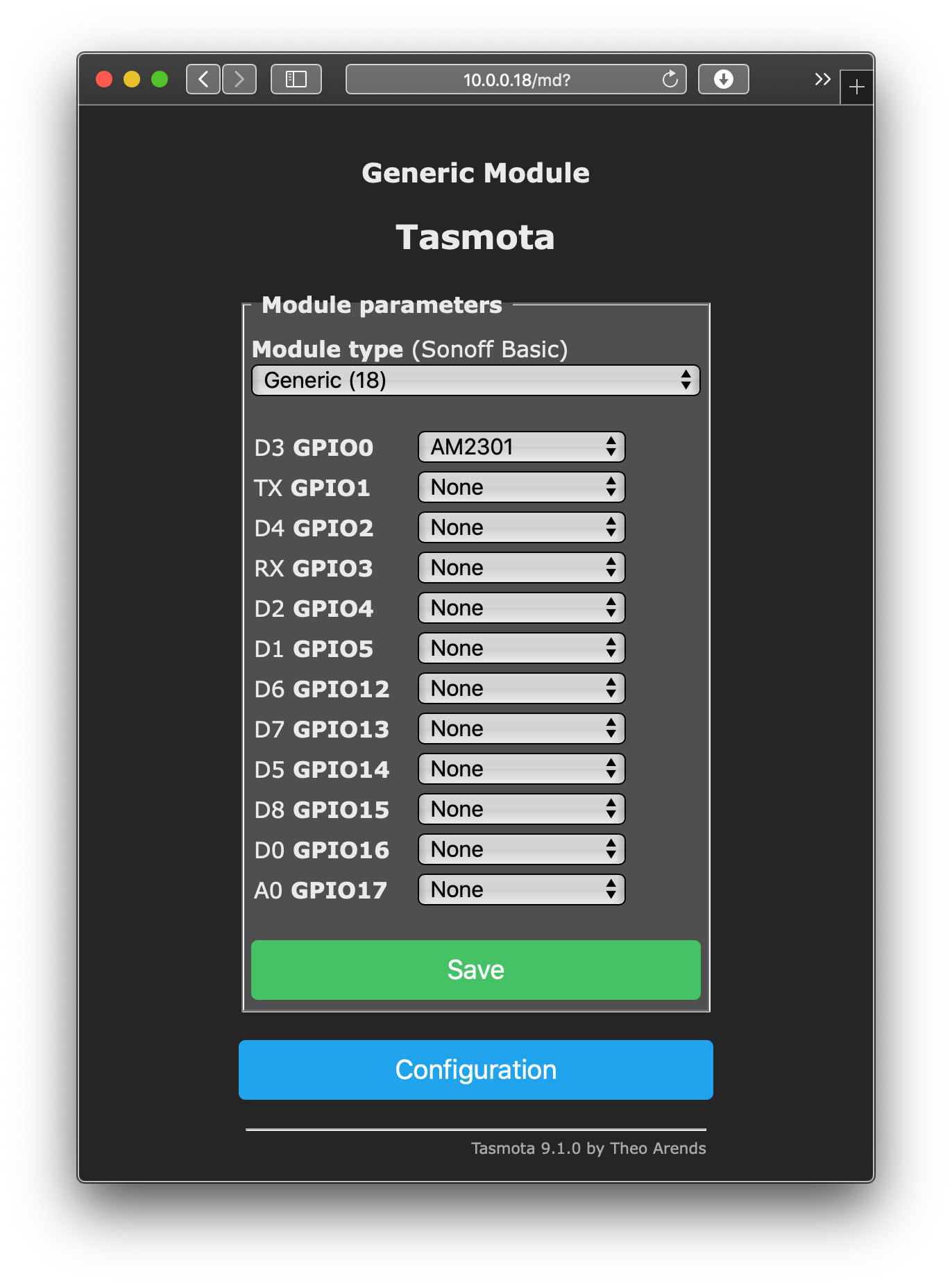
Configuration > Configure ModuleAfter restarting, you should now see the measurements on the web page served by the ESP8266, and you could stop here, but that's not what I'm all about. I like my iPhone, I like my iPad, and I want to connect this DIY sensor to HomeKit.